Dongguan Magnetoelectronics Technology Co. Ltd..
Contact: Miss Zhang
Tel: 0769-22336260
Mailbox: 3468754465@qq.com
Website: www.magpresee.com
Address: Room 102,No.7 Xingye Road,Low Chung,Gaobu Town,Guangdong,Dongguan City,Guangdong province
With the continuous development of the motor manufacturing process, modern stamping technology has cited the process methods for manufacturing the motor core. Now it is more and more accepted by the manufacturer of the motor, and the processing methods for manufacturing the motor core are also more and more advanced.
In foreign countries, generally advanced manufacturers of motors, all use modern stamping technology to punch iron core parts. In China, the processing method of stamping iron core parts with modern stamping technology is being further developed, and this high-tech manufacturing technology is becoming more and more mature. In the motor manufacturing industry, the advantages of this manufacturing motor process have been taken seriously by many manufacturers.. Using modern stamping technology to make iron core parts and the original use of ordinary molds and equipment to make iron core parts, compared with the characteristics of high automation, high dimensional accuracy, long die service life, etc., suitable for the large number of stamping parts production. As the multi-position step injection die is a punch of a large number of processing processes on a die, the manufacturing process of the motor is reduced, and the production efficiency of the manufacturing motor is improved.
Today, the development of the economy, the production technology of fixed rotor iron core is also constantly improving, according to the current actual situation, for everyone to introduce its production methods and structure.

Fixed rotor core structure
The utility model provides a step rotor structure, which comprises a shell body, a fixed element and a rotor. The stator is arranged on the rotor and the stator and rotor is located inside the shell. Where the rotor comprises a screw and a magnetic component, the screw is arranged with a central shaft, the central shaft forms at least one ring groove, and a connecting layer is arranged on the ring groove; The magnetic component is provided with a container part, and the central shaft of the housing part is accommodated, and the connecting layer on the ring groove of the central shaft is joined with the inner wall of the magnetic component. The rotor of the stepper rotor structure of the utility model combines a screw with a magnetic component by means of a point adhesive, so that the binding density of the screw and a magnetic component is consistent, so that the rotor can withstand the centrifugal force and seismic force generated by the magnetic field of the stator and the rotor. And can maintain the lightness of the rotor, so that the rotor maintains precise positioning during rotation.
Methods of production
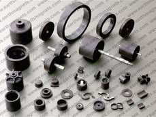
The fixed rotor core consists of a magnetic yoke iron and a rubber magnet located in a magnetic yoke iron, in which the surface of the guide magnetic yoke iron of the rubber magnet has one or more patterns. This fixed rotor core manufacturing method selects a flat surface rubber magnet and forms one or more patterns on one side of the surface of the rubber magnet. After that, the surface with the pattern of the rubber magnet faces outwards. The rubber magnet is bent into a shape corresponding to the inner side of the magnetic yoke iron, and the rubber magnet is placed in the magnetic yoke iron.